


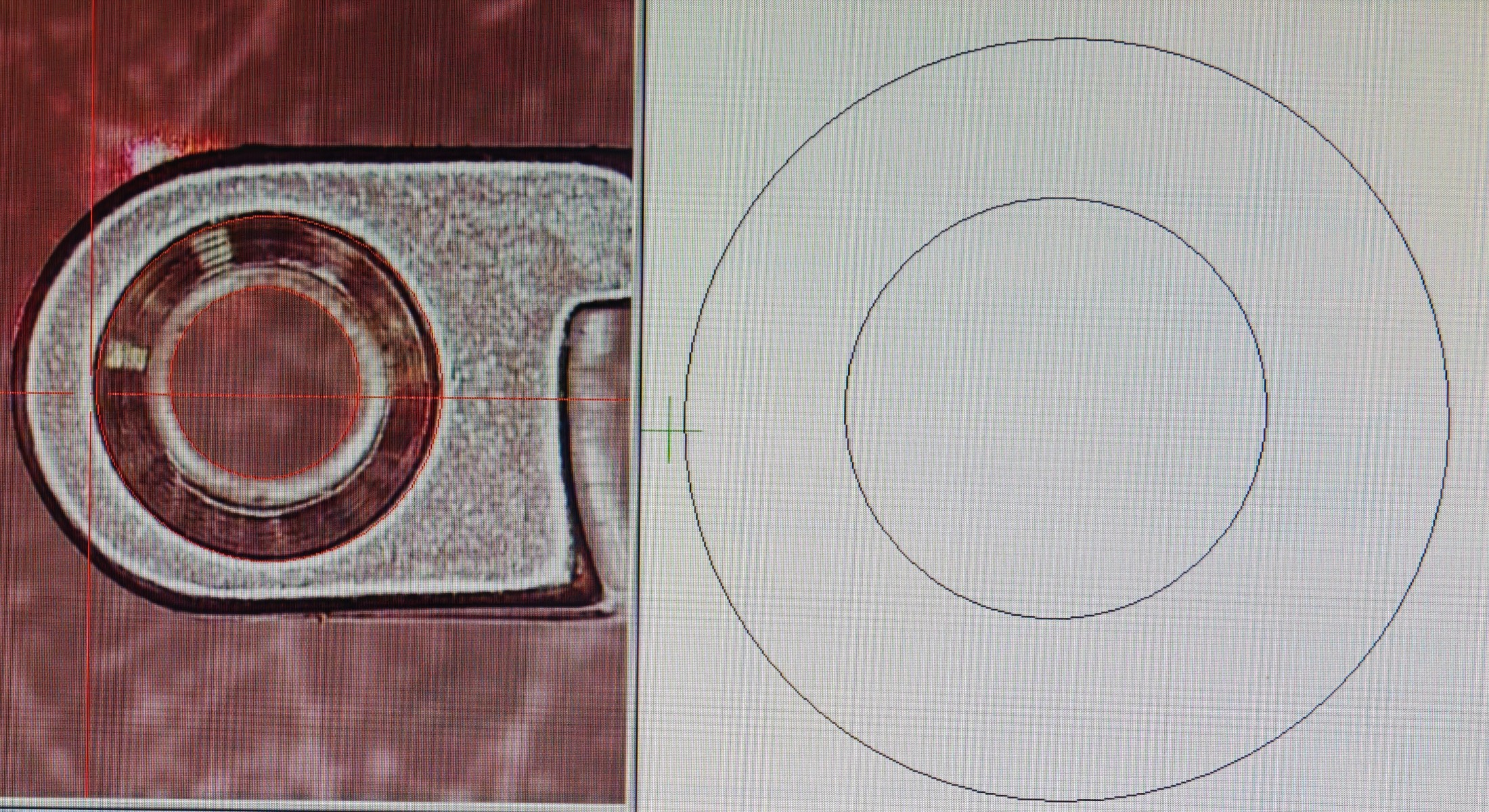
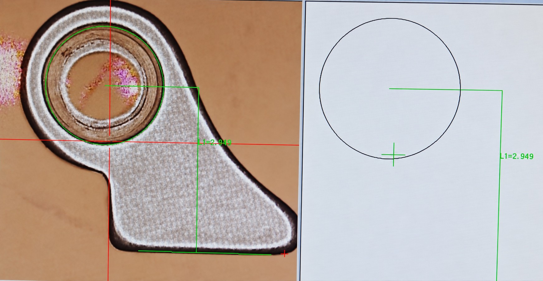
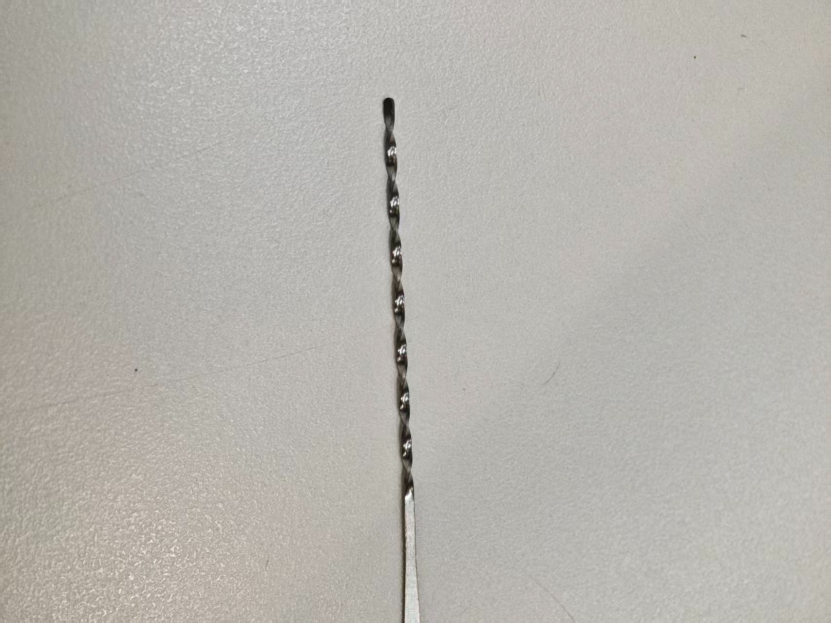
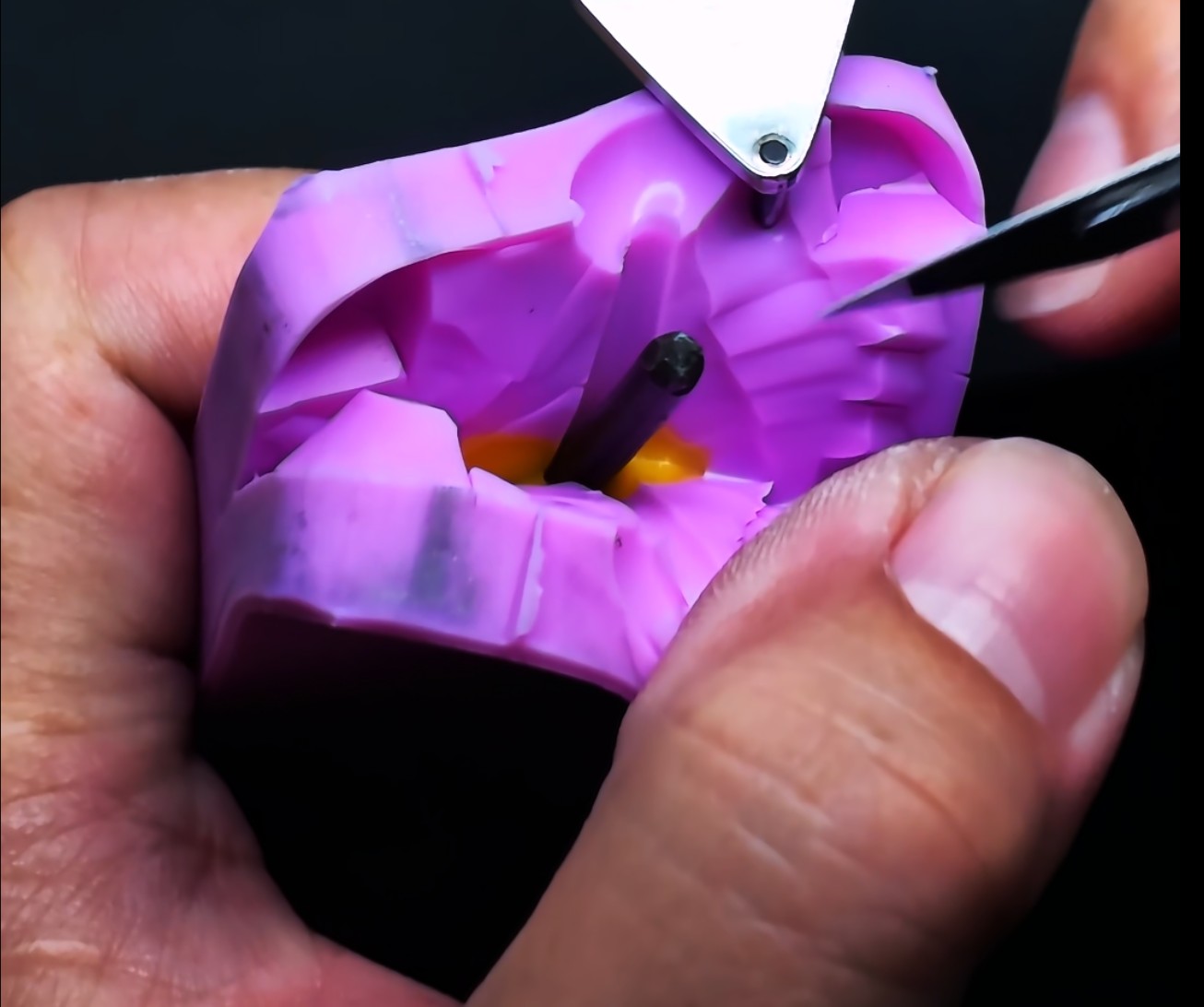
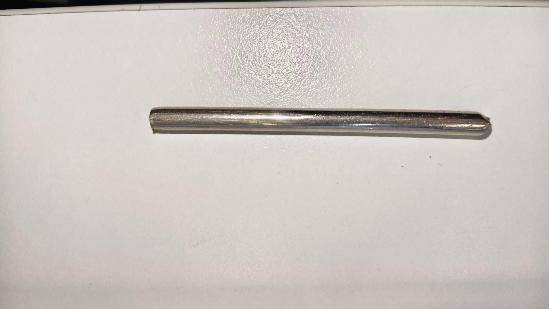
Eyewear parts are small and varied in shape, and in the past they were mostly judged with magnifying glasses and measuring tools. Digital measuring projectors magnify and project the outline of a part onto a screen, making edges, shapes and positional relationships more intuitive.
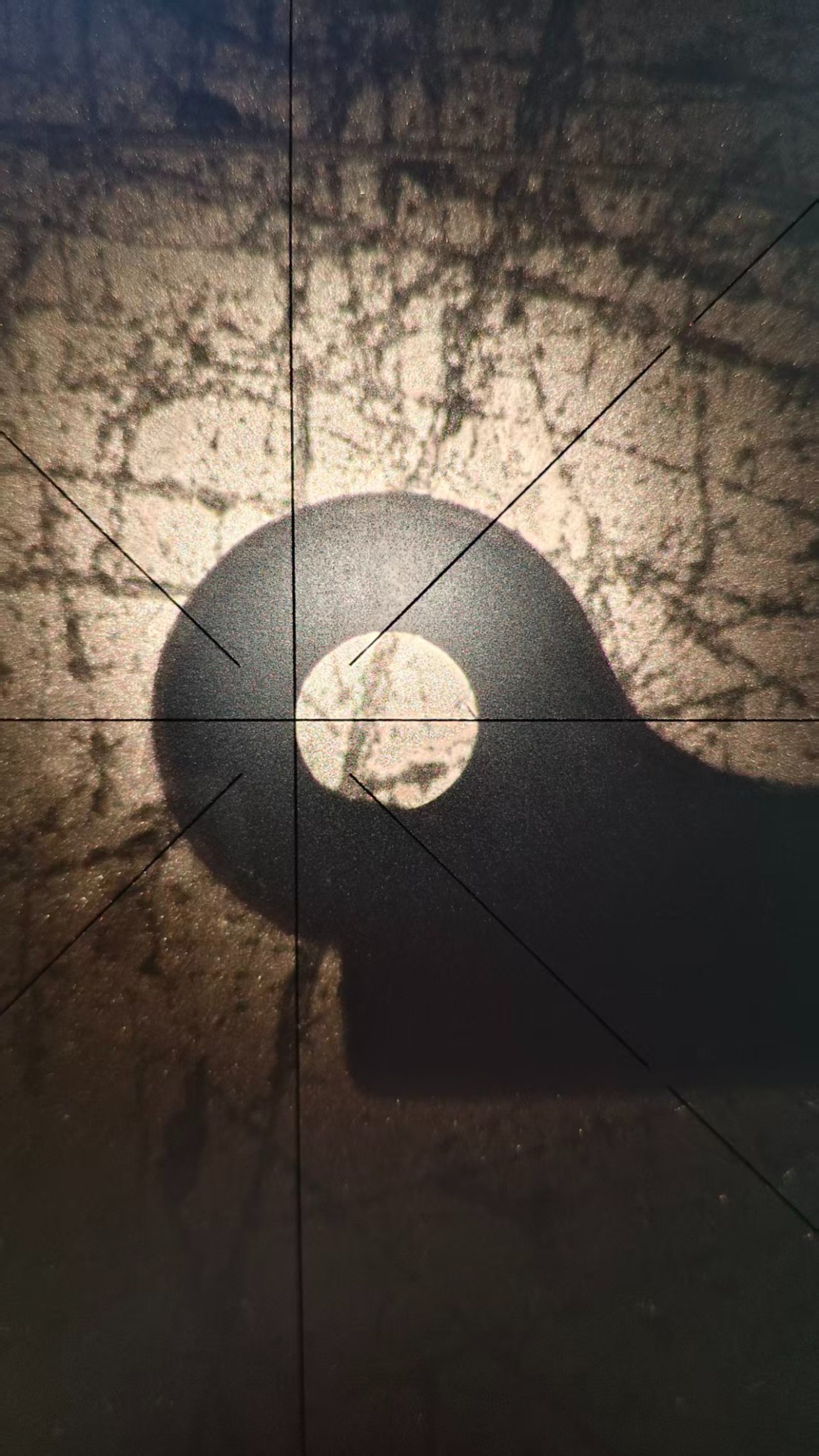
The working principle of a digital measuring projector is roughly as follows: a light source transmits (or reflects) illumination onto the workpiece, and the objective lens magnifies and projects the outline onto the projection screen; the stage is moved so that the image on the screen coincides with the crosshair to complete alignment, and the displacement is converted by a linear scale into pulse counts, with the digital display directly reading the X, Y coordinates and angle—that is, optical magnified projection + precision displacement digital display———Reference GB/T 24762-2009 "Geometrical product specifications (GPS)—Acceptance and reverification tests for imaging measuring instruments"
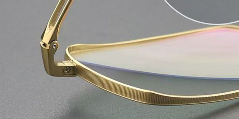
It can be used for parts such as temples, frames, clamp openings, hinges, bridges, and end pieces. By printing the drawing at 10:1 on transparent material and aligning it with the projected outline, one can see whether the shape is offset, whether there is excess flash (burr) on the edges, and whether the outline matches the drawing. This method is suitable for small, irregularly shaped parts, can reduce visual deviation, and can also be used for tolerance measurement and parts other than eyewear, including medical supplies.
Its role is not limited to finished product inspection. Making "seeds", confirming preliminary data, checking mold trial parts, and sampling tests can all use projected outlines and measurement data for comparison. Once preliminary data deviates, the problem will be carried into the mold and subsequent production; the earlier it is found, the more rework and losses can be reduced. The "Casting Process" also emphasized this point. It provides observable and recordable images and data, but cannot replace drawing requirements and confirmed samples.
Here are some classic cases during use: when the diameter is known, align the cross centerline with one edge of the circle, check that there is no gap, then move to the other side to verify the diameter, and then move to half the diameter position to assist in judging the center of the circle. This is only preliminary positioning; critical dimensions should still use professional tools and confirmed measurement methods.
This article only introduces usage scenarios and basic functions, and does not expand on operating steps. Actual use requires selecting methods according to part shape and measurement purpose. If you would like to learn more, or find anything inappropriate in this article, please contact us.
Thank you for watching